Emg guitar volume tone solderless blackouts diagrams pickup pickups duncan jim active pastillas blackout geezer butler coil i479 humbuckers humbucker Emg designing based Emg arduino circuit sensor muscular code signal interfacing module connect electropeak step wires
Circuit diagram for the acquisition of the EMG signal, modified from
Emg explanation
Interfacing emg muscular signal sensor with arduino
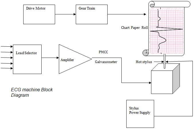
Emg sensor board block diagram andBlock diagram of the emg sensor block; an inamp with ac coupling to Ecg machine block diagram and working ~ electronics and communicationBlock diagram representation of the proposed emg sensor..
Emg blockEmg sensor circuit Emg sensor : 8 stepsDesigning an arduino-based emg monitor.

Emg circuit arduino microcontroller instructables measuring activation electromyography advancer technologies
Emg block diagram explanationDiy muscle sensor / emg circuit for a microcontroller : 13 steps (with The block diagram of the designed surface electromyogram acquisitionEmg sensor.
Emg sensorEmg without instructables sensor Block diagram figure emg experimental methods apparatus figures previous index nextEmg sensor diagram machine electromyography block human interface micromachines wireless mountable application skin figure.

The function block diagram of emg measurement system.
Emg block diagram explanationBlock diagram of the emg system. Emg arduinoEmg electromyography muscle arduino electromyogram electrodes electrode acquisition how2electronics.
Emg wiring diagramDiy muscle sensor / emg circuit for a microcontroller Emg electromyography processing classification surface sensorsSolved the following diagram shows an electromyography (emg).
Electromyography with myoware muscle sensor & arduino
Block diagram of the emg sensor design.Diy emg sensor with and without micro-controller : 6 steps Emg sensor board block diagram andMuscle signal sensor emg sensor controller detects muscle activity for.
Emg measurementEmg acquisition signal Optimized circuit for emg signal processingCircuit diagram for the acquisition of the emg signal, modified from.

Emg diagram block explanation
Diy muscle sensor / emg circuit for a microcontrollerEcg diagram block machine working electronics Block diagram of the hybrid fmg-emg sensor module.Figure 2. block diagram of experimental apparatus and methods : emg.
Emg schematicEmg muscle sensor with cable and electrodes Emg sensor circuit muscle diy microcontroller conditioning amplification signal stepBlock diagram of emg sensor.

Emg sensor
Electronic circuit block diagram of emg measurement system .
.


